

A common current meter, as usually built-in in typical multimeters measures the current as a voltage drop across an internal shunt resistor. A usual digital 3 ˝ digit - voltmeter has a lowest current range of 200 mV, accordingly the voltage drop across the internal shunt resistor rises up to 200 mV when the current corresponds to the full range.
Example: Your digital voltmeter got a lowest voltage range of 200 mV. When switching to the current range 200 ľA, Ohm's law (U=R*I) applies: In that range, the internal resistance must be 200 mV/200 ľA = 1 kOhm. Consequently, when your current reading is e.g. 100 ľA, the voltage drop between the terminals of the ammeter is U = R x I = 1 kOhm x 100 ľA = 100 mV.
When measuring the current in common electric circuits, this voltage drop can be disregarded. Concerning electrochemical potentials, a voltage drop of 100 mV is nearly enormous: remember that Tafel slopes at ambient temperature may vary by 29 mV per current decade. This example shows drastically that an ammeter for electrochemical measurements should (ideally) have an internal resistance of 0 (zero) Ohms.
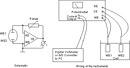
To achieve this, special "zero - resistance - ammeters", also called active current sinks (CS), are used. However, any potentiostat can be used as such an active current sink, and it is very simple to do so. Simply connect electrode WE1 to the electrode termoinal of your potentiostat, adn WE2 to both reference electrode plug and counter electrode plug. Now, set the potential to 0 mV, and switch to potentiostatic mode (counter electrode on).
What happens? A current is displayed on the potentiostat's current meter, and a corresponding voltage is fed to the current output terminal. The voltage between WE1 and WE2 is zero! So, we measure the current between two electrodes, that are kept on the same potential. That is, what ar ZRA does! The current range that you are using, does not influence the measurement, nor cause any potential drop.

Fig. 4: Potentiostat as Zero - Ohm - Ammeter (Current Sink)
Polarity: The polarity of the current that passes the working electrode is positive if the meter deflects to the right (positive) side.
If the internal current range does not give the required resolution, you can introduce an external range resistor (see fig. 4, schematic left side). Then, the current is defined by the voltage at the CE terminal and the external range resistor, according to
I = U / R,
where R is the external range resistor. As higher the external resistor is, as more it will pick up noise. For R = 1 MOhm, I = U / R = 1 V/ľA. A capacitor across the external range resistor will be useful to reduce noise. The time constant of R x C should be in the order of ms for currents down to 1 ľA, for lower currents R x C should be in the order of 100 ms up to 1 s. Example: 1 nF x 1000 MOhm = 1 s might be good for measuring currents below 1 nA.
Bank Elektronik -
Intelligent Controls GmbH
Hubertusstr. 38
D-35415 Pohlheim
Tel. +49 - 6403 - 60 98 60
Fax +49 - 6403 - 60 98 622
e-Mail: info [at] bank-ic.de